

Wireless Underground Sensor Networks
The project is supported by DFG.
Staff Members of the Project
- Prof. Dr.-Ing. Wolfgang Gerstacker
- Dipl.-Ing. Steven Kisseleff
International Collaborations
Introduction
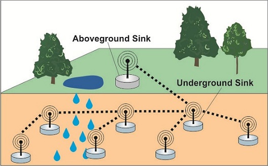
Wireless underground sensor networks (WUSNs) are an emerging and promising research area. The goal is to establish efficient wireless communication between wireless devices that operate below the ground surface. Significant attention to WUSNs capabilities for monitoring various underground conditions is caused by the variety of existing and potential applications.
Possible Applications
|
|
|
|
|
|
|
|
|


Basic Concept
The underground environment has a unique nature. It has a significant and direct impact on the communication performance, creating challenges for hardware design and system deployment.
Performance of EM-based WUSNs is very limited due to harsh propagation conditions. Magnetic induction (MI)-based WUSNs, which make use of magnetic antennas implemented as coils, improve the transmission range due to a much lower pathloss.
System Model
1. Basic structure of MI transmissions (Direct MI)
For the analysis of channel capacities of MI-WUSNs, a reliable and comprehensive system model is needed. The well known effects of frequency splitting (multiple resonances) need to be incorporated in a common pathloss and noise descriptions.
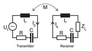
Block diagram of the direct transmission includes a transmitter resonance circuit with a voltage source Ut and a receiver resonance circuit with a load impedance ZL. Each resonance circuit includes additionally a (frequently assumed air core) inductance coil with inductivity L, a capacitor with capacitance C, and a resistor R (which models the copper resistance of the coil). The coupling between transceiver coils is related to the mutual inductance M.
The voltage Ut yields a current flow through the transmitter coil, such that a quasi-static magnet field appears and influences the receiver coil. As known from the theory of magnetism, this magnet field induces therefore a voltage in the receiver coil, which triggers the current flow in the receiver. The voltage at the load impedance ZL is viewed as the received signal of the communication system.
A characteristical property of direct MI transmission scheme is a strong dependancy of the pathloss on the soil conductivity described by the eddy currents effect (similar to the skin effect in metals), which yields an optimal operation at very low resonance frequency for sufficient large transmission distances.
In general a highly frequency-selective pathloss for the MI based signal transmissions results. An important observation is furthermore that the thermal noise signals coming from the utilized resistors is not white as frequently assumed. The reason is the voltage division in the receiver circuit, which depends on the circuit impedances.
2. Point-to-Point MI waveguides
Several passive relays can be deployed between two transceiver nodes in order to extend the transmission range. This idea was originally proposed in context of MI based metamaterials. Using the same strategy as for the direct MI, the current flow in the second coil yields a secondary magnet field, which influences the third coil and induces a voltage there. Hence, this signal propagation can be seen as a so called traveling MI wave. Since misalignments and limited precision of the system deployment are inevitable, power reflections at every device need to be considered, which makes the concept of the „wave“ not very practical.
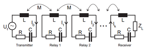
Block diagram of the MI-waveguide includes additionally (k -1) passive relays, which are placed equidistantly between the transceivers.
For MI waveguides, the optimal resonance frequency can be chosen much higher in order to increase the magnetic induction between each two relay coils, yielding much lower pathloss between these coils and for the whole waveguide in general. However, the choice of the resonance frequency is not trivial (in general non-convex) and constrained by the physical elements of the system:
- parasitic effects in coils, e.g. capacitances (especially in multi-layer coils), resistance;
- parasitic effects in loaded capacitors (resistances);
- minimum capacitance of the loaded capacitor, e.g. C≥1pF.
These constraints have a strong impact on the signal attenuation and frequency-selectivity of the pathloss functions and can lead to a significant performance degradation.
3. Design of WUSNs
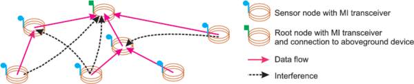
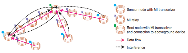
Basically, the main task of the WUSNs is related to data collection. Therefore, the tree-based network architecture seems to be best suited for this purpose. We restrict ourselves to the simply connected spanning trees, since it is preferable to avoid circulating data in the network due to the limited data rate in the underground communication systems. As it is common in WSNs, each sensor (root) node not only transmits its own sensed data, but also relays the data from the (leave) nodes connected to it. For this, we apply a decode-and-forward relaying scheme in our works. The data from the whole network is then guided to the sink node, which either stores it or retransmits to an aboveground device. An example of the network deployment is given in the Figure.

An example of a WUSN with 50 sensor nodes (black circles), which are wirelessly connected (black lines), including a sink node (red square).
An important performance metric for the network design is the throughput. However, there are several definitions of the network throughput depending on the application. We focus on the minimum (bottleneck) throughput among all network links, which is defined as follows
![]() where Ci represents the achievable data rate (usually given by the channel capacity) of link i, Nstreams, i stands for the number of data streams to be served by the root node i and Ninterferers, i denotes the number of relevant interfering signals, which may disturb the packet reception.
where Ci represents the achievable data rate (usually given by the channel capacity) of link i, Nstreams, i stands for the number of data streams to be served by the root node i and Ninterferers, i denotes the number of relevant interfering signals, which may disturb the packet reception.
There are two possible approaches for the design of MI-WUSNs: direct MI based and MI waveguides based. These two approaches differ in the propagation characteristics and properties of the signal transmission. Hence, the design and optimization strategies differ as well.
In order to simplify the manufacturing of the devices and to reduce the costs, we choose all passive elements to be identical in all used devices. Hence, in direct MI based WUSNs, all sensor nodes have identical structure and sets of passive elements. For the MI waveguides based WUSNs, we need to distinguish between the actual transceiver devices and the less complex relay devices for the waveguides. Hence, devices of the same type (transceiver or relay) have identical structure.
System Optimization
1. Point-to-Point transmission, cf. [1]
A commonly used criteria for the design of a point-to-point signal transmission is the channel capacity, which can be calaculted using the well known Shannon’s capacity equation:
![]() where B is the width of the transmission band, Pt(f) is the transmit power density spectrum complying with the waterfilling rule, Lp(f) is the frequency-selective pathloss function, and Pn(f) is the noise power density spectrum. As mentioned earlier, both Lp(f) and Pn(f) heavily depend on the system parameters like resonance frequency, coil windings, conductivity of the soil, etc. Hence, an optimization problem for maximizing C under practical design constraints needs to be formulated and solved. In general, this optimization is non-convex and a multi-scale algorithm is used for finding the optimal solution.
where B is the width of the transmission band, Pt(f) is the transmit power density spectrum complying with the waterfilling rule, Lp(f) is the frequency-selective pathloss function, and Pn(f) is the noise power density spectrum. As mentioned earlier, both Lp(f) and Pn(f) heavily depend on the system parameters like resonance frequency, coil windings, conductivity of the soil, etc. Hence, an optimization problem for maximizing C under practical design constraints needs to be formulated and solved. In general, this optimization is non-convex and a multi-scale algorithm is used for finding the optimal solution.
2. WUSN with direct transmission, cf. [4]
Due to the quasi-omnidirectional propagation of the magnet field in direct MI transmission based WUSNs, there is a strong impact of the interference signals coming from different sensor nodes.
It seems to be a good strategy to exploit the polarization property of the field in order to separate these streams. This separation, called interference polarization, is done via rotating the axes of the coils in the optimal direction, which results from the global network optimization. For this, an iterative algorithm is proposed, which reduces the impact of the interfering signals and improves the signal quality for the bottleneck link. In addition, the system parameters are optimized in order to further reduce the pathloss and increase the data rate.
3. WUSN with MI waveguides, cf. [3]
For the MI waveguides based WUSNs, the signal transmission is highly directional. Due to the optimal set of system parameters, which differs from that of the direct MI based WUSNs, the interference between two neighboring sensor nodes not linked via MI waveguides is negligible. Hence, this signal transmission reminds on the powerline communications scenario.
Correspondingly, the network topology is one of the key parameters to be optimized. Traditionally, for the design of the tree-based MI-WUSNs, the minimum spanning tree (MST) approach is chosen, which is optimal in many cases. However, its optimality holds only under not always bearable assumptions, like weak coupling between relay coils (although the opposite is desired) or equal number of interfering signals per transceiver. Hence, an advanced topology design is needed. Finding the optimal topology for the MI waveguides based WUSNs, so called advanced spanning tree (AST), is an important part of the global network optimization and is carried out using an interative algorithm, which improves the performance with respect to the bottleneck throughput. Furthermore, the polarization of the magnet field can be exploited in order to improve the coupling between the relay coils of the bottleneck waveguide. Here, the difficulty is due to the power reflections at the waveguides connected to the same transceiver. In order to avoid high losses of signal power, all coils (transceivers and relays) can only be rotated at once. For the global optimization it yields the full search of the common axes orientation.
Signal Processing
Realistic modulation schemes for Point-to-Point transmissions, cf. [5]
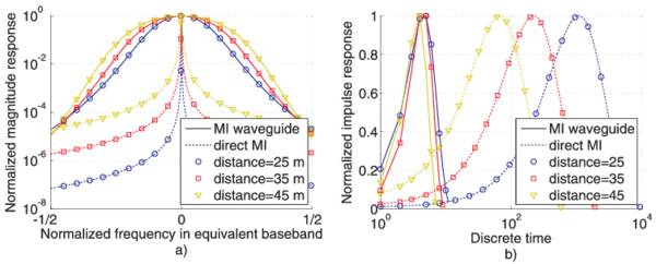
In order to enable the signal transmission and reception, more realistic transmit/receive/equalization filters and modulation scheme need to be developped for the MI transmissions. The typical channel transfer functions and corresponding impulse responses are shown in the Figure.
Due to the aforementioned difference in nature between direct MI transmission and MI waveguides based approaches, the modulation and filter design for these two schemes may differ as well.
In general, we assume a smooth band-limited waveform for pulse shaping, which complies with the √cos impulses. For the receive filter we utilize the whitened matched filter, such that an additive white Gaussian noise results after sampling in the receiver. For the optimal design, we utilize the capacity achieving minimum mean-squared error (MMSE) based decision feedback equalizer (DFE). For the digital filters we choose the maximum filter length of 100 taps. Furthermore, we utilize M-QAM modulation, which can be selected by the designer based on the signal quality measurements and target error rate.
Direct transmission
For the direct MI transmission, the equivalent discrete-time impulse response is very long (up to several 10000 channel taps!). The reason is a very high frequency-selectivity of the transmission channel despite a large bandwidth as it results from the optimization. Such impulse responses cannot be equalized using filters with only 100 taps. In particular, for the feedback filter of the DFE the filter length must be at least the same length as the impulse response (\approx 10000 taps) in order to provide a sufficient performance. However, such long filter lengths are not practical. In order to reduce the frequency-selectivity of the channel, a three-band based frequency-division approach is proposed, which provides the achievable data rates close to the channel capacity while keeping the effort of signal processing low.
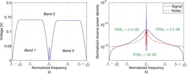
In addition, the power allocation can dramatically improve the performance oft he system, such that results of up to 70% of channel capacity can be reached.
MI waveguides
For the MI waveguides, the channel impulse response is not too long („only“ 10-15 taps). A different problem arises in context of modulation scheme selection. Due to a very limited bandwidth of this scheme, all transmit power is allocated to a very small set of frequencies around the resonance frequency. Therefore, a high signal-to-noise ratio (SNR) results, which enables modulations of up to 18 bit/symbol! Such modulation schemes are however not practical, especially for the small sensor devices. Therefore, a bandwidth expansion algorithm is proposed, which converts the benefit of a high SNR into the benefit of a larger bandwidth.
Design of the modulation schemes for MI-WUSNs
The design of the modulation scheme for the whole MI-WUSN can be done based on the results provided for the point-to-point transmissions. However, following the principle of utilizing the the same set of system parameters, a common modulation scheme (or a small set of possible modulation schemes) needs to be determined, which may maximize the achievable data rate of the bottleneck link. In addition, the signal bandwidth must be chosen identical for all network links in order to ease the implementation of the transmit and receive filters. Therefore, an optimal network design should combine the approaches of network optimization with that of the modulation and bandwidth selection. This can be done using a full search in the space of all available system parameters.
Transmitter-side channel estimation for Point-to-Point transmissions, cf. [6]
Due to a strong interconnection between any two magnetic induction enabled devices, there is an impact of the receiver circuit and the MI channel on the current flow in the transmitter. By introducing an additional load impedance in the transmitter and connecting it to the signal reception components, this impact can be detected. Of course, an offset signal not related to the transmission channel needs to be excluded first. The result can be utilized for the transmitter-side channel estimation, such that the transmit power and its distribution can be adjusted automatically without explicit feedback signaling. Two approaches are proposed, which either collect many samples of the desired signal and combine them by means of maximum likelihood in order to obtain the channel attenuation or exploit the mismatch between the filters of the DFE, which occur in case of sudden changes of the attenuation.
Limited feedback channel estimation in MI-WUSNs (disaster detection)
Publications
Our publications
[1] Kisseleff, S. and Gerstacker, W. H. and Schober, R. and Sun Z. and Akyildiz, I. F. (2013).
Channel Capacity of Magnetic Induction Based Wireless Underground Sensor Networks under Practical Constraints.
IEEE Wireless Communications and Networking Conference (WCNC) 2013, Shanghai, China. 2603 – 2608.
![]()
[2] Sun, Z. and Akyildiz, I.F. and Kisseleff, S. and Gerstacker, W. (2013).
Increasing the Capacity of Magnetic Induction Communications in RF-Challenged Environments.
IEEE Transactions on Communications. 61 (9), 3943 – 3952.
![]()
[3] Kisseleff, S. and Gerstacker, W. and Sun, Z. and Akyildiz, I.F. (2013).
On the Throughput of Wireless Underground Sensor Networks using Magneto-Inductive Waveguides.
IEEE Globecom 2013, Atlanta, GA, USA.
![]()
[4] Kisseleff, S. and Akyildiz, I.F. and Gerstacker, W. (2013).
Interference Polarization in Magnetic Induction based Wireless Underground Sensor Networks.
IEEE PIMRC 2013- SENSA Workshop, London, UK.
![]()
[5] Kisseleff, S. and Akyildiz, I.F. and Gerstacker, W. (2014).
On Modulation for Magnetic Induction based Transmission in Wireless Underground Sensor Networks.
IEEE International Conference on Communications (ICC), Sydney, Australia, 2014.
![]()
[6] Kisseleff S. and Akyildiz I.F. and Gerstacker W., (2014).
Transmitter-Side Channel Estimation in Magnetic Induction based Communication Systems.
IEEE BlackSeaCom, Kishinau, Moldova, 2014.
![]()
[7] Kisseleff S. and Akyildiz I.F. and Gerstacker W., (2014).
Disaster Detection in Magnetic Induction based Wireless Sensor Networks with Limited Feedback.
IFIP Wireless Days, Rio de Janeiro, Brazil, 2014.
![]()
[8] Kisseleff S. and Akyildiz I.F. and Gerstacker W., (2014).
Throughput of the Magnetic Induction based Wireless Underground Sensor Networks: Key Optimization Techniques.
IEEE Transactions on Communications. 62 (12), 4426 – 4439.
![]()
[9] Kisseleff S. and Akyildiz I.F. and Gerstacker W., (2015).
Digital Signal Transmission in Magnetic Induction based Wireless Underground Sensor Networks.
IEEE Transactions on Communications. 63 (6), 2300 – 2311.
![]()
[10] Kisseleff S. and Sackenreuter, B. and Akyildiz I.F. and Gerstacker W., (2015).
On Capacity of Active Relaying in Magnetic Induction based Wireless Underground Sensor Networks.
IEEE International Conference on Communications (ICC), London, UK, 2015.
![]()
[11] Kisseleff S. and Akyildiz I.F. and Gerstacker W., (2015).
Beamforming for Magnetic Induction based Wireless Power Transfer Systems with Multiple Receivers.
accepted for presentation at IEEE Global Communications Conference (Globecom), San Diego, CA, USA.
Further literature
- I. F. Akyildiz and E. P. Stuntebeck, „Wireless underground sensor networks: Research challenges,“ Ad Hoc Networks (Elsevier), Vol. 4, No. 6, pp. 669-686, November 2006.
- I. F. Akyildiz, Z. Sun and M. C. Vuran, „Signal Propagation Techniques for Wireless Underground Communication Networks,“ Physical Communication (Elsevier) Journal, Vol. 2, No. 3, pp.167-183, September 2009.
- E. Stuntebeck, D. Pompili and T. Melodia, „Underground Wireless Sensor Networks Using Commodity Terrestrial Motes,“ poster presentation at IEEE SECON 2006, Reston, VA.
- L. Li, M. C. Vuran and I. F. Akyildiz, „Characteristics of Underground Channel for Wireless Underground Sensor Networks,“ in Proc. Med-Hoc-Net ’07, Corfu, Greece, June 13-15, 2007.
- M. C. Vuran and I. F. Akyildiz, „Cross Layer Packet Optimization for Wireless Terrestrial, Underwater and Underground Sensor Networks,“ in Proc. IEEE Infocom’08, April 2008.
- Z. Sun and I. F. Akyildiz, „Underground Wireless Communication using Magnetic Induction,“ in Proc. IEEE ICC 2009, Dresden, Germany, June 2009.
- Z. Sun and I. F. Akyildiz, „Optimal Antenna Geometry Analysis of MIMO Communication Systems in Underground Tunnels,“ in Proc. IEEE Globecom’09, Honolulu, USA, November 2009.
- Z. Sun and I. F. Akyildiz, „Channel Modeling and Analysis for Wireless Networks in Underground Mines and Road Tunnels,“ IEEE Transactions on Communications, Vol. 58, No. 6, pp. 1758-1768, June 2010.
- Z. Sun and I. F. Akyildiz, „Magnetic Induction Communications for Wireless Underground Sensor Networks,“ IEEE Trans. Antennas and Propagation, Vol. 58, No. 7, pp. 2426-2435, July 2010.
- Z. Sun and I. F. Akyildiz, „Connectivity in Wireless Underground Sensor Networks,“ in Proc. of IEEE SECON 2010, Boston, USA, June 2010.
- M. C. Vuran and I. F. Akyildiz, „Channel Modeling and Analysis for Wireless Underground Sensor Networks in Soil Medium,“ Physical Communication Journal (Elsevier), Vol. 3, No. 4, pp. 245-254, December 2010.
- Z. Sun and I. F. Akyildiz, „Deployment Algorithms for Wireless Underground Sensor Networks using Magnetic Induction,“ in Proc. of IEEE GLOBECOM 2010, Best Paper Award (11 out of 4614 submissions), Miami, USA, December 2010.
- Z. Sun, P. Wang, M. C. Vuran, M. A. Al-Rodhaan, A. M. Al-Dhelaan, and I. F. Akyildiz, „MISE-PIPE: Magnetic Induction-based Wireless Sensor Networks for Underground Pipeline Monitoring,“ Ad Hoc Networks Journal (Elsevier), Vol. 9, No. 3, pp. 218-227, May 2011.
- Z. Sun and I. F. Akyildiz, „A Mode-Based Approach for Channel Modeling in Underground Tunnels under the Impact of Vehicular Traffic Flow,“ submitted to IEEE Transactions on Wireless Communications in April 2010, revised in January 2011 and May 2011.
- Z. Sun, I. F. Akyildiz, and G. P. Hancke, „Capacity and Outage Analysis of MIMO and Cooperative Communication Systems in Underground Tunnels,“ submitted to IEEE Transactions on Wireless Communications in October 2010, revised in March 2011 and June 2011.
- Z. Sun, I. F. Akyildiz, and G. P. Hancke, „Dynamic Connectivity in Wireless Underground Sensor Networks,“ submitted to IEEE Transactions on Wireless Communications in March 2011, revised in July 2011.
- Z. Sun and I. F. Akyildiz, „Spatio-Temporal Correlation-Based Density Optimization in Wireless Underground Sensor Networks,“ to appear in Proc. of IEEE GLOBECOM 2011, Houston, USA, December 2011.